Difference between revisions of "Analysis of Step 1"
| Line 1: | Line 1: | ||
The verification involves a direct comparison with the analytical solution. For this purpose, analytic fields for | The verification involves a direct comparison with the analytical solution. For this purpose, analytic fields for | ||
| − | '''velocity''' (x- and y-components) and '''vorticity''' <math>(\ | + | '''velocity''' (x- and y-components) and '''vorticity''' <math>(\partial_x v - \partial_y u)</math> at <math>t=10 \tau_{ref}</math> are presented in Fig. 3. It should be noted |
that both '''YALES2''' and '''DINO''' used 642 '''grid points''' for this test case, while '''Nek5000''' employed 82 | that both '''YALES2''' and '''DINO''' used 642 '''grid points''' for this test case, while '''Nek5000''' employed 82 | ||
'''spectral elements of order 8''', which results in 64 '''discretization points''' in each direction. The velocity profiles along both centerlines of | '''spectral elements of order 8''', which results in 64 '''discretization points''' in each direction. The velocity profiles along both centerlines of | ||
Revision as of 15:30, 26 August 2020
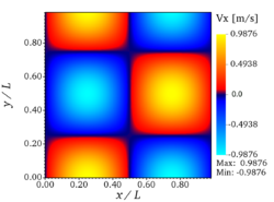
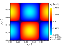
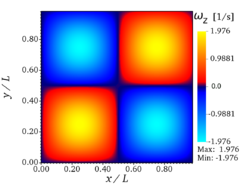
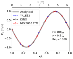
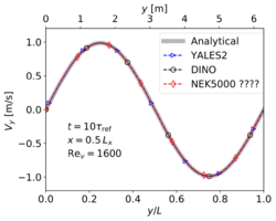
The verification involves a direct comparison with the analytical solution. For this purpose, analytic fields for velocity (x- and y-components) and vorticity at are presented in Fig. 3. It should be noted that both YALES2 and DINO used 642 grid points for this test case, while Nek5000 employed 82 spectral elements of order 8, which results in 64 discretization points in each direction. The velocity profiles along both centerlines of the domain at are shown in Fig. 4. It can be observed that the three codes give perfect visual agreement 14 with the analytical solution. Table 3 present the analytical maximal velocity at (as computed from Eq. 2) and the values obtained with the three codes, as well as the associated relative error: it is observed that the maximal deviation is less than for the three codes.
| Analytical | YALES2 | DINO | Nek5000 | |
|---|---|---|---|---|
| 0.987271 | 0.987583 | 0.987565 | ???? | |
| 0 [Ref] | 0.03% | 0.03% | - |
This configuration, although quite far from any realistic flame, is nevertheless an excellent manner to verify the numerical procedure. It can be used to check the obtained discretization order in space and time and to quantify numerical dissipation, as documented for instance in Figure 5 of [1].
You can see on the figures above the analytic fields of x-velocity, y-velocity, and vorticity, respectively (from left to right), at for Step 1 (verification step).
Comparing the results of the three codes with the analytical solution for the 2-D Taylor-Green vortex (Step 1). Left: xcomponent of velocity. Right: y-component of velocity.
References
- ↑
A. Abdelsamie, G. Fru, F. Dietzsch, G. Janiga, D. Thévenin, Towards direct numerical simulations of low-Mach number turbulent reacting and two-phase flows using immersed boundaries, Comput. Fluids 131(5):123--141, 2016, BibtexAuthor : A. Abdelsamie, G. Fru, F. Dietzsch, G. Janiga, D. Thévenin
Title : Towards direct numerical simulations of low-Mach number turbulent reacting and two-phase flows using immersed boundaries
In : Comput. Fluids -
Address :
Date : 2016
